
Introducing surface loads in CYPE 3D and in CYPECAD’s integrated 3D structures is carried out in the same way.
In order to introduce surface loads in CYPE 3D or in CYPECAD’s integrated 3D structures, users must define a panel on which they can define loads over its entire surface and loads applied in certain areas of the panel’s surface.
The loads applied to the entire surface of the panel are introduced when the panel is defined. The tools that users can use to introduce and edit these loads and the panels that contain them are located in the Loads drop-down menu and are as follows:
- Introduce panels
- Delete panels
- Edit loads on panels
- Modify the distribution direction of the loads
The tools available to users for introducing and editing surface loads applied to certain areas of the panel surface are located in the Loads drop-down menu and are as follows:
- Introduce panels
- Edit surface loads
- Copy surface loads
- Delete surface loads
There is another option related to the surface loads of the panel and to the surface loads of defined areas of the panel:
- Activate/deactivate surface load assignment
There are also two dialogue boxes that appear when introducing or editing panels and surface loads whose features are worth mentioning:
- Loads on panel dialogue box:
This appears when the Introduce panels or Edit loads on panels options are used. - Surface loads dialogue box:
This appears when the Introduce surface loads, Edit surface loads or Copy surface loads options are used.
Options in the Loads menu for managing panels and surface loads
Below, the aforementioned options in the Loads drop-down menu are defined in detail:
Introduce panels:
This allows users to introduce a panel formed by a closed polygon that may have loads applied over its entire surface (either uniform or that vary in height) or surface loads associated with certain areas of its surface. In the panel, users must indicate the direction of the one-way distribution that both the load of the panel and the surface loads contained in it will have. For example, on the roof of a warehouse, the direction applies to the purlins, if what is to be loaded are the transverse frames.
Delete panels:
Deletes the selected panels and thus their lists of loads.
Edit loads on panels:
Allows users to modify the lists of loads applied to one or more selected panels. If the panel is not parallel to the global XY plane, the dialogue box shows two tabs, one for uniform loads and one for those that vary in height. However, if it is horizontal, it only shows the list of uniform loads.
The program assumes that all loadcases other than wind loads always have a positive downward direction (towards the negative z-coordinates) regardless of the positive load vector; whereas, for wind loadcases, they are applied perpendicularly to the panel bearing in mind the direction of the vector of positive load.
The loads are introduced with their sign.
This option also allows users to match loads amongst different panels if multiple selections have been carried out.
Modify the distribution direction of the loads:
Using this option, users can modify the distribution direction of the loads on a panel. Once the panel has been selected, in order to indicate the new direction, one of the auxiliary straight lines defining the sides of the panel must be selected.
Introduce surface loads:
This option allows users to introduce a surface load as a polygonal shape. Loads can be uniform or can vary depending on the height if the surface is not horizontal.
This surface distributes the loads depending on the direction of the panel to which it belongs. A surface load belongs to a panel in which it is completely contained, and so it is not permissible for a load to overlap with more than one panel. An example of surface load application can be the loading of a panel with different wind pressures.
Upon introducing a new surface load, the program detects if it overlaps with an existing panel. If it does not, the user is asked whether or not a distribution panel is to be generated in the same way as the created surface. This new panel has a distribution direction given by the straight line joining the first two points of the introduction of the surface, even though this direction can be modified later with the Modify the distribution direction of the loads option.
Edit surface loads:
Allows users to modify one or more of the surface loads corresponding to the visible loadcase. Only those surfaces that have loads applied in the visible loadcase are shown onscreen.
Copiar cargas superficiales:
Using this option, a new surface load is created based on the data of a previously created load. The new surface load will have the same shape and position as the existing load, so it will only be necessary to indicate the loadcase, the type and the load values for this new surface load.
Delete surface loads:
Deletes one or more surface loads from among those corresponding to the visible loadcase.
Activate/deactivate surface load assignment:
Indicates whether or not one or several bars can be loaded by panels or surface loads. If a bar is deactivated, it will not accept loads in any loadcase. Ties are bars that are always deactivated.
Deactivated bars are marked onscreen in dashed lines.
By default, all bars (except ties) support surface loads unless this option is used to deactivate them.
CLoads on panel dialogue box
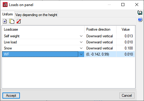
The Loads on panel dialogue box appears when the Introduce panels option (after geometrically defining the panel and indicating the distribution direction of the loads) or Edit loads on panels option (after selecting the panel that contains the loadcases) is used.
In this dialogue box, if the panel being edited is horizontal (parallel to the global XY plane) it can only have uniform loads; if it is not, two tabs will appear, one to show the list of uniform loads and the other for loads that vary in height.
An unlimited number of loads can be shown for each type of load in one or several loadcases. For uniform loads, users simply have to indicate the value and sign for each one of them. For those that vary in height, the values and signs of the loads in the bottom Z and top Z coordinate of the panel must be indicated.
The data in the “Positive direction” column cannot be modified, but are simply informative via the Downward vertical, Upward vertical texts or the coordinates of a unit vector that represents the direction of a positive load. It should be noted that, in the case of loadcases other than wind loadcases, a load is positive if its direction is downwards (negative z coordinates), regardless of the direction of the aforementioned vector. However, for wind loadcases, the defined loads refer to this vector.
The list format for loads on panels makes it easy to introduce and review data for loads. At the same time, with the “Edit loads on panels” option, users can quickly assign loads from one panel to another.
Surface loads dialogue box
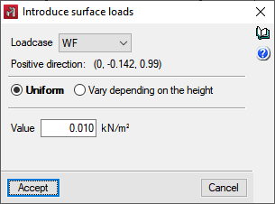
When the Introduce surface loads, Edit surface loads or Copy surface loads options are used, the following dialogue box appears.
The editing of surface loads is by loadcase, i.e. a surface load is a load on a certain loadcase.
When this option is selected, only the surface loads of the visible loadcase are shown onscreen. If the loadcase to which the load is applied is modified, the load will be hidden as it is not in the visible loadcase.
Just like the panels, the load of a surface load can be uniform or vary in height. For uniform loads, users simply indicate the value and sign for each of them; whereas, for loads that vary in height, they must indicate the values and signs of the loads on the bottom Z and top Z coordinate of the surface.
In the dialogue box, the positive direction of the load is indicated by the Vertical downwards or Vertical upwards text or by the coordinates of a unit vector, in order to enter the correct sign of the load. It should be noted that, in the case of loadcases other than wind loadcases, a load is positive if its direction is downwards (negative z coordinates), regardless of the direction of the aforementioned vector. However, for wind loadcases, the defined loads refer to this vector.