

By default, CYPECAD does not contemplate the alternation of live loads, so that the live load defined in the floor plan is applied to the entire surface area occupied by the slab at the same time.
To analyse the effect of some spans with loads and others without, the live loads must be entered manually by occupying those spans and assigning them to different load cases.
To do this, the floor can be divided into two types of live loads, like a chessboard, with one type of live load in the white squares and another type of live load in the black squares. A more thorough alternation could also be made by dividing the surface area of the floor into four types of live loads (surrounding the columns); however, the more types of live loads you define, the more combinations will be generated, and the slower the analysis and checking of each structural element will be.
Both cases are discussed below.
Alternating two live loads
For a case with two load situations, follow these steps:
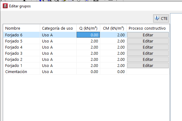
- In the on plan live load (in "Column Definition", from "Introduction > Floors/Groups > Edit groups", or in "Beam Definition", from "Loads > Loads in groups") specify that the live load is equal to 0:
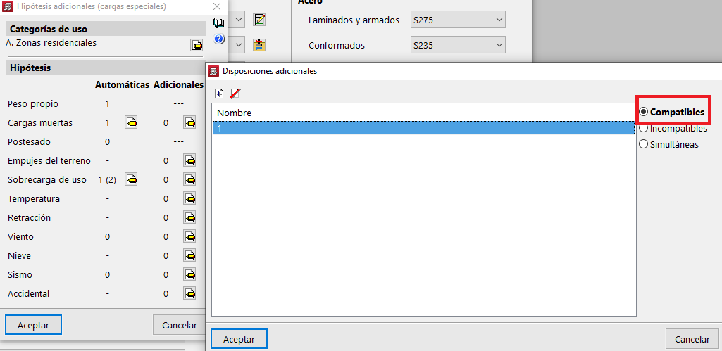
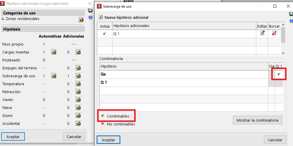
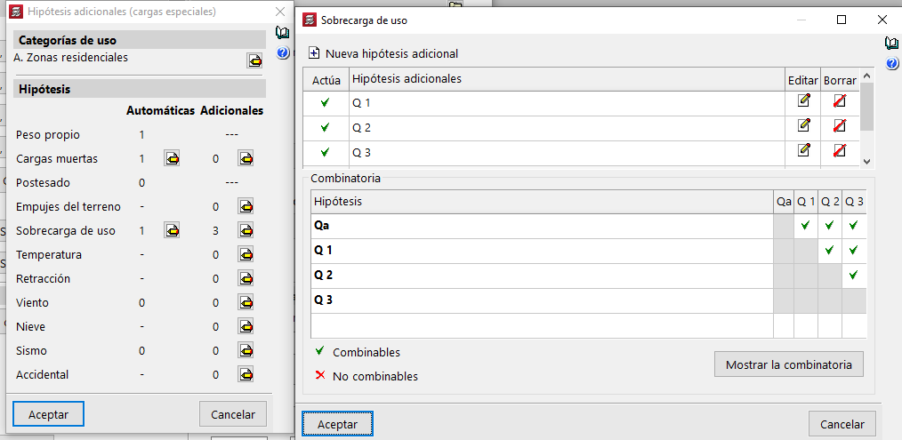
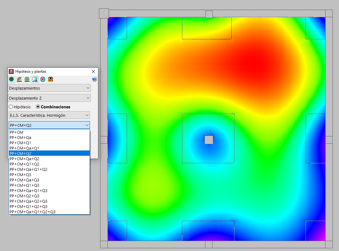
- Under "Project > General data > Additional loadcases", the second load case must be compatible or combinable with the existing live load. This second live load can be either automatic or additional:
When adding an automatic load case (using the "Additional dispositions" table), it should be marked as "Compatible".
When adding a "New additional loadcase", it must be defined as "Combinable" by marking the corresponding cell in the "Combination" table.
Thus, in either case, the two load cases will act at the same time in some combinations. The program will also create combinations with only one of the load cases and with none of them (since they are live loads).
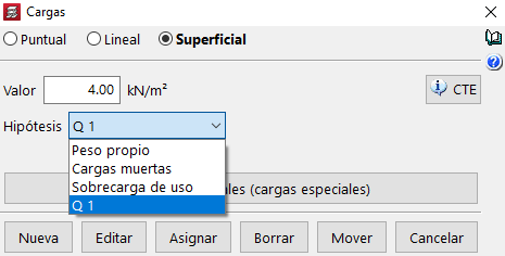
- Then, draw the loads as surface loads (from "Loads > Loads > Surface", if you wish to freely enter the geometry of surface loads or from "Loads > Surface loads on slabs", if the slab is divided into spans coinciding with the geometry of loads), occupying the entire slab, and associating each span with each of the two live loads that have been defined:
In the image above, the blue surface loads correspond to the Live load (automatic), and the green surface loads correspond to the Q1 load case (entered earlier as "Additional"):
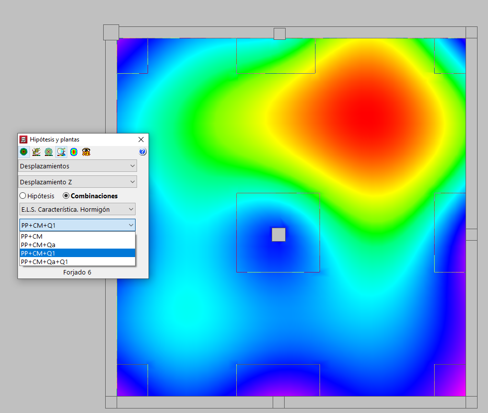
Thus, during the analysis, CYPECAD will consider these load cases via the different combinations. In this case:
SW + DL (self weight and dead load, with no live loads)
SW + DL + Qa (with automatic live load)
SW + DL + Q1 (with additional live load)
SW + DL + Qa + Q1 (with both live loads)
A simple example of alternating two live loads can be downloaded and viewed via this link. To open it, use the option "File > File manager > Decompress".
Alternating four live loads
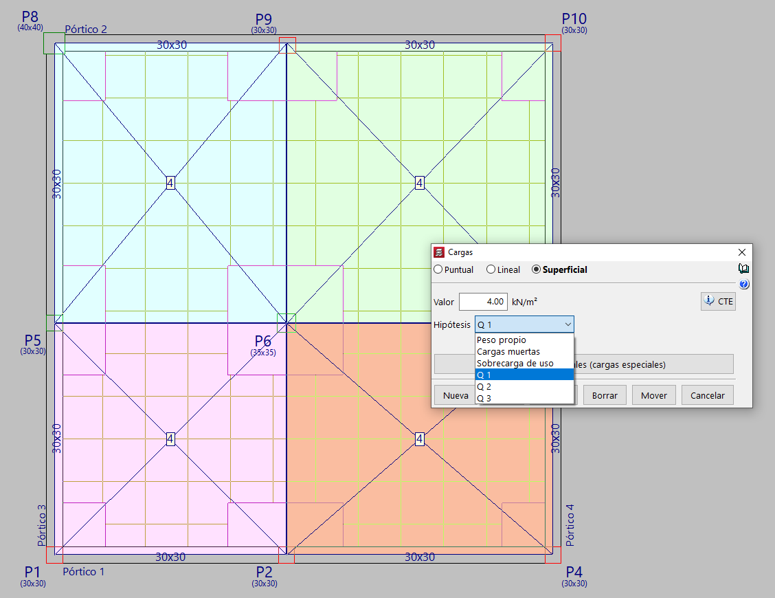
To alternate four live loads, the floor slab should be divided into four zones, applying a live load in each zone that is assigned to a different live load.
To do this, first, create three additional live loads (Q1, Q2, Q3), which can be combined with each other and with the automatic loadcase Qa:
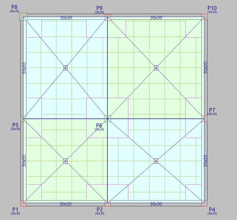
Second, draw four surface loads, each of them assigned to the "Live load" load case (Qa), "Q1", "Q2" and "Q3". In the image, they are shown in four different colours:
The combinations generated by the program are as follows:
A simple example of alternating four overloads can be downloaded and viewed via this link. To open it, use the option "File > File management > Decompress".