
The following modelling recommendations are a best practice guide to enable more robust computer modelling in IFC Builder in order to reduce the number of issues and errors after exporting to programs such as CYPETHERM EPlus.
Intersections between vertical elements
We recommend that the intersections between external walls and partitions are made using the reference lines. In properly resolved intersections, no broken lines appear. The reference lines can be consulted by going to the "Walls and partitions > Move" option and are shown on the screen as green lines.
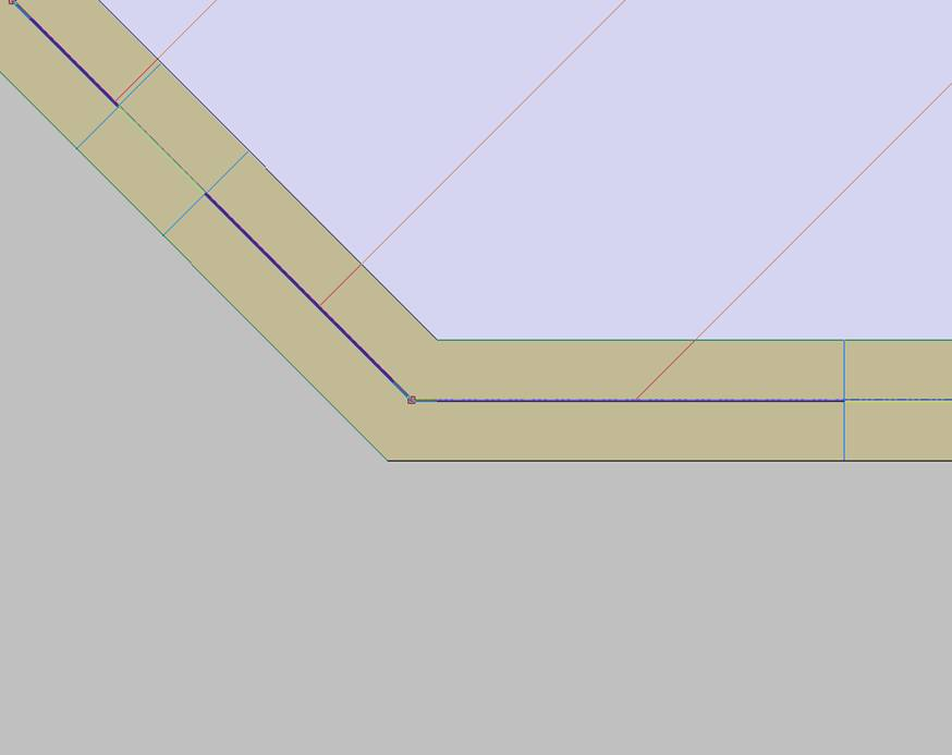
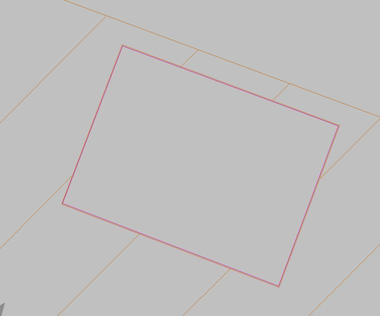
The following image shows a poorly resolved wall intersection:
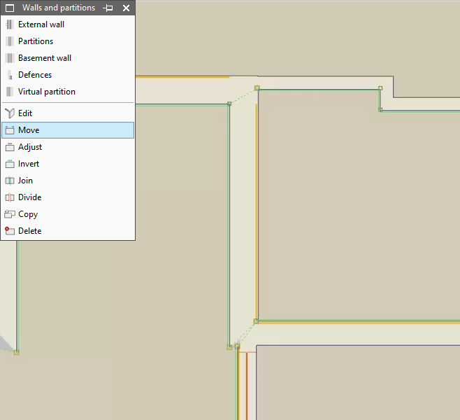
In these cases, the program decides to try to solve the intersection automatically and generates the dotted dashed lines that appear on the screen. However, this automatic operation results in less reliable geometries, especially when exporting to other programs. To improve the model, using the "Adjust" and "Move" tools, make sure to correctly resolve the encounters to achieve geometries similar to those in the following image:
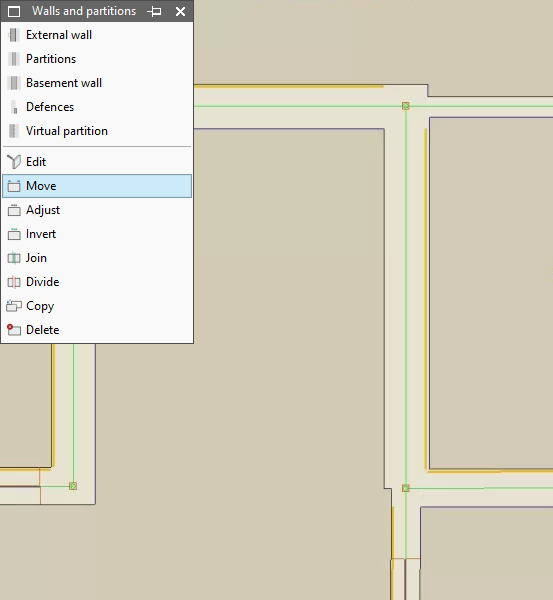
In the image above, you can see that the partitions are now defined on axes and are on the reference line of the other partitions. The dashed lines have disappeared.
Optionally, it is recommended to use the "Walls and partitions > Adjust" option as an aid and define the vertical elements at the axis of the reference line.
Intersections between vertical and horizontal elements
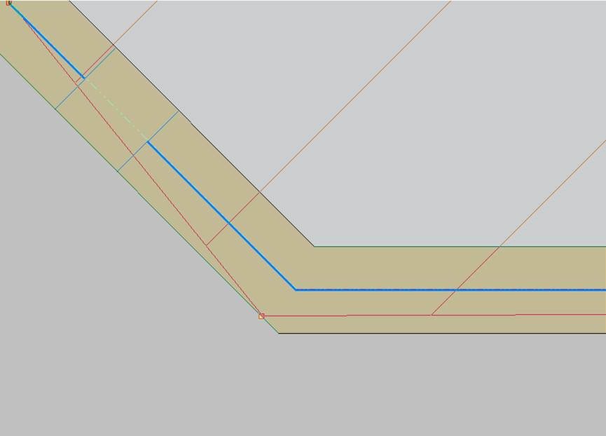
We recommend that the floor slab edges coincide with the reference line of the external walls. To do this, the "Floor slabs > Move" option is used. The clamping points (shown with the yellow square symbol) of the vertices of the slab must coincide with the gripping points of the envelopes, which define their reference line.
For example, the following is an example of a poorly executed intersection between an external wall and a floor slab:
To resolve this, the floor slab and the external wall have been moved, making them coincide:
Geometry adjustment between floors
We recommend that the floor slab edge and the reference line of the external wall of a given floor should coincide with the reference line and the edge of the floor slabs of the floor below and, where applicable, of the floor above.
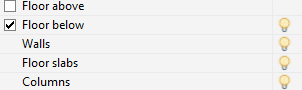
The position of the elements of other floors can be displayed by activating the "Floor below" or "Floor above" checkboxes on the left side of the IFC Builder interface.
For example, the following intersection is poorly resolved, since the reference lines of the elements that appear on the work floor do not coincide with the lines of the floor below. The outline of the walls on the lower floor is shown as a grey dotted line, and the edge of the floor slab on the lower floor is shown as a dotted line:
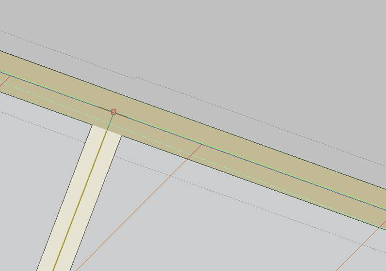
To correct this, the layout must be equalised on both floors using the program's snaps and the "Move" option on both floors.
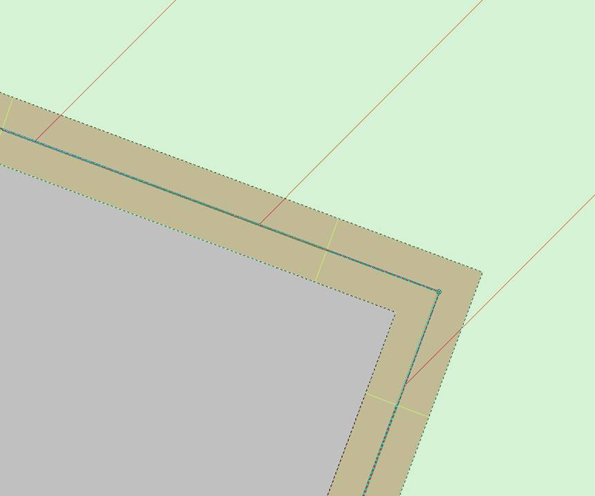
The following image, on the other hand, shows a well-resolved intersection, as the walls and floor slabs of both floors coincide. When activating "Floor below" or "Floor above", the dashed and dotted lines coincide with the outline and layout of the elements of the current floor:
Floor slab openings
We do not recommend adding floor slab openings too close to the floor slab outline, leaving little space between the line defining the floor slab outline and the line defining the perimeter of the floor slab:
If these openings are needed in the model, the outline of the floor slab itself will be used to create the opening area. In the case of the image above, the decision has been made to delete the opening from "Edit", "Delete", and then manipulate the edge of the floor slab with the "Insert", "Divide" and "Move" options under "Floor slabs".Dividir” y “Mover«, dentro de “Forjados”.
With these options, gripping points can be created for the outline of the floor slab and the geometry of the slab can be adjusted: