

In CYPE 3D, users may find the following warning: “The compression axial force is excessive and exceeds the critical buckling axial forces” when accessing the “Analysis” menu, clicking on the “Check elements” or “U.L.S checks” options and hovering the mouse pointer over the bars:
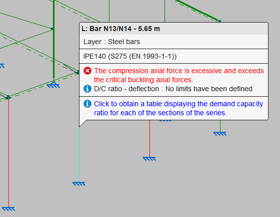
This warning is related to non-compliances in the compressive resistance and combined bending and axial resistance checks on the bar, where the value of the critical buckling axial forces is concerned.
When analysing this value, section properties such as the moment of inertia as well as the defined effective buckling length value in the two planes of the section are considered.
This problem can be solved by carrying out the following actions:
1. Reducing the analysed compression forces. To do this, the applied loads can be revised or a new design of the structure can be considered to unload the bars affected by the problem.
2. Modifying or increasing sections. This is carried out from the "Bar" menu and the "Describe" option, choosing larger sections from the same series or using a different series of sections. The variations of the moment of inertia and the section area will lead to changes in the analysis of the critical axial force.
3. Reducing the value of the buckling length in a justified way. Due to the influence of the buckling length value in the calculation of the critical elastic buckling axial force, a reduction of its value can be considered. To do this, from the "Bar" menu, select the "Buckling" option and modify the parameters in the "Assign buckling length (xy plane)" and "Assign buckling length (xz plane)" sections. The program obtains the buckling length by multiplying the defined buckling coefficient by the bar length.
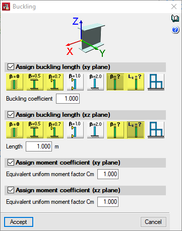
In the image, the options that allow users to define a value of the buckling coefficient (β) smaller than the unit, which is the default value, are shown on the left. Alternatively, the buckling coefficient or a buckling length as an absolute value can be entered directly by selecting the options "β=?" and "Lk=?" on the right-hand side.
The buckling length represents the clear span of the bar measured between the structural supports and its reduction must be duly justified by the designer.
For example, in the case of an embedded column in a continuous façade able to resist structural forces or a beam embedded in a floor slab, a buckling coefficient value can be used in the plane of the façade or floor slab equal to zero, assuming that the bar is braced over its entire length.
If the column or beam is supported by specific bracing elements spaced a certain distance apart, e.g. roof or façade purlins with adequate structural capacity, the buckling length can be approximated by using the distance between these elements.
Editing the buckling length in only one of the planes is usually sufficient to achieve a significant variation in the critical elastic buckling axial force.