


The creation of rotated views allows different orthogonality axes to be used per view, making it easier to enter elements into the views while maintaining the general orientation of the model. This way, users can enter parts of the model that are not aligned with the cardinal directions (north, south, east or west), such as façades or partitions.
This method is valid for any program using the 3D work environment.
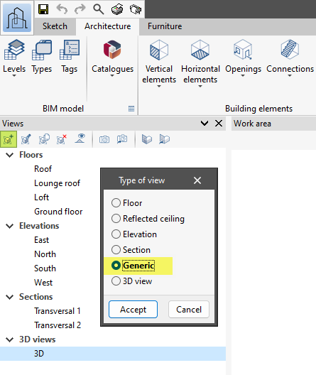
To do this, in the "Views" section on the left-hand side of the interface, click on "Create", in the "Type of view" panel select "Generic" and click "Accept":
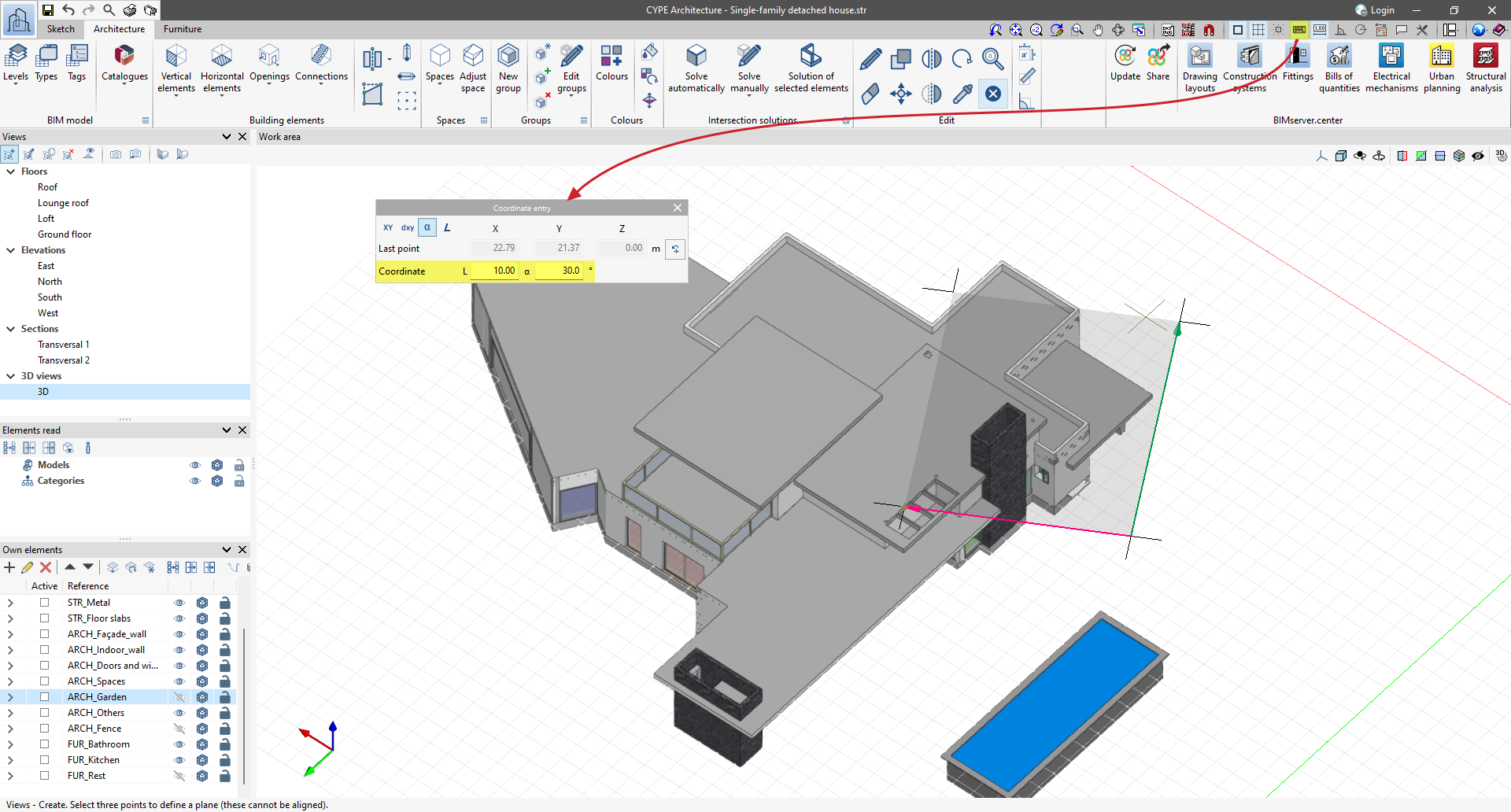
Click on the first point on the model (this will determine the height position of the new view). Next, select the "Coordinate entry" option at the top of the interface and select "Polar coordinates" (the X, Y and Z values displayed correspond to those of the last point entered). Now, type in an arbitrary "L" value and an "α" (alpha) angle that may correspond to the offset from north. Press the Enter key while the cursor is blinking in the last field; this completes the entry of the X-axis of the working plane of the new view. Click on another point in the work area to enter the Y-axis of the working plane of the new view (its position relative to the X-axis will also determine the Z-axis of the new view).
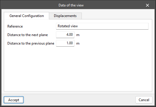
Then, finish configuring the view by entering data such as the "Reference" or display distances ("Distance to the top plane" and "Distance to the bottom plane"), and click "Accept" to finish.
The new rotated view will be available under "Views" in the "Generic" section. The work plane, templates and orthogonality systems of this new view are adapted to the angle entered so that it is possible to work comfortably at other angles when entering the elements in this view.
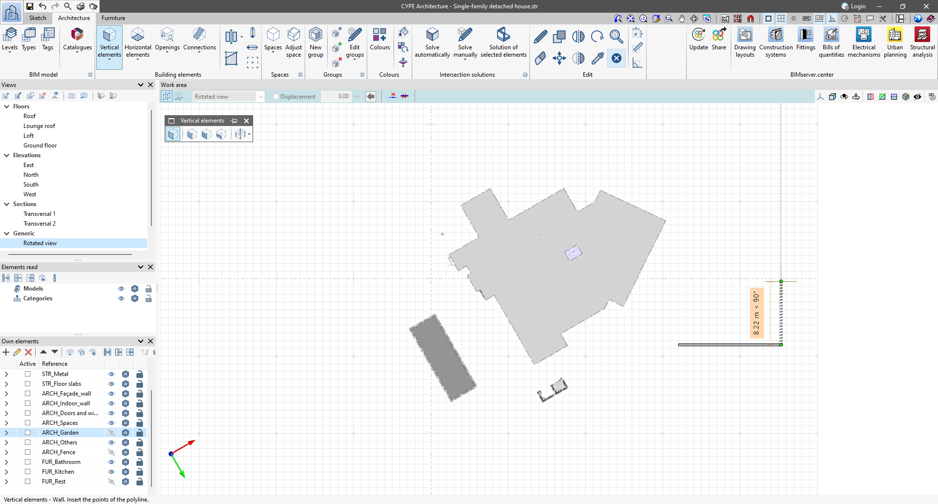
You can use the "Go to the workplane" option in the top tools group in the "Views" section to match the on-screen orientation to the orientation of the axes in the new view. The global axes of the model, which remain unrotated, appear in the bottom left-hand side of the view.
To work at other angles, you can create and use as many generic rotated views as you need within the same model.
If you use this method in CYPE Architecture, when exporting to BIMserver.center, we keep the criterion that the north follows the global green Y-axis, which also corresponds to the axis of the same colour of the working plane of the original 3D view by default. Therefore, the use of rotated views will not affect the direction of north. Thus, no further adaptations would be necessary in other programs.