
To access the column editor in CYPECAD after the analysis of a job, open the “Results” tab and select the “Columns/Shear walls” menu at the top of the interface. Then click on “Edit” and click on the desired column on the plan. Columns with checking errors will be coloured in red.
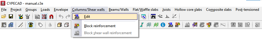
This allows users to access the “Edit columns” window, where the advanced column editor is displayed if they are working with a code that allows its use. With this editor, users can consult the forces, sizing and checks carried out automatically by the program on all the columns in the job and on all its spans. Also, groups of columns can be organised and resized, the reinforcement or the steel sections used can be modified and all the modifications made can be checked, generating detailed checklists afterwards.
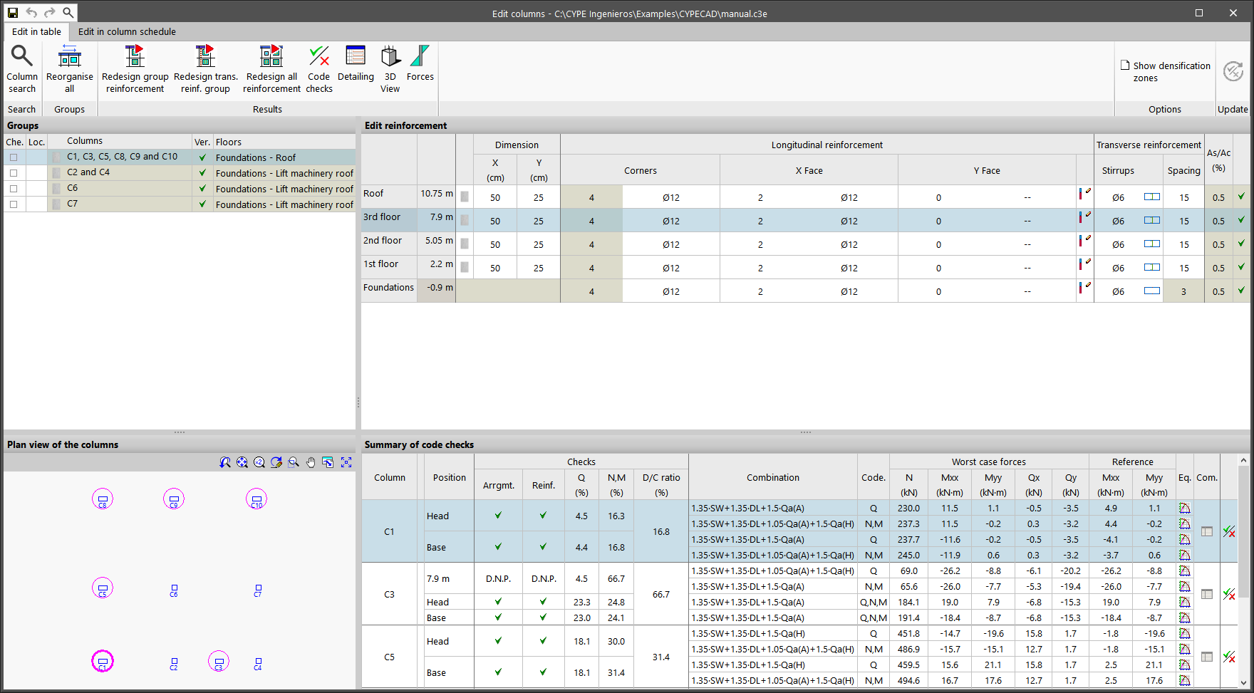
The window displays two tabs, “Edit in table” and “Edit in column schedule“. Either of these editing interfaces allows the necessary checks and modifications to be made on the columns. They differ in editing possibilities and results review and in the view on which they are carried out. Users can choose any of them, as the information is linked.
Edit in table
The “Edit in table” tab displays the information in four sections.
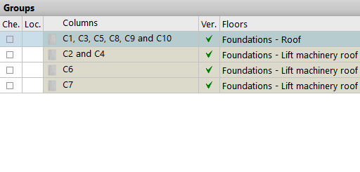
Groups
Firstly, the “Groups” section in the top left-hand corner allows users to select between the different sets or groups of columns that the program has created during the analysis. The columns in the same group share the same cross-section geometry, number of floors and reinforcement. In this table, it is marked whether the group has been “Checked” or “Locked” if no changes are to be allowed. It is also indicated whether or not the group “, is “Verified” in accordance with the specifications of the selected standard, and the “Floors” it passes through.
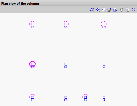
Plan view of the columns
The “Plan view of the columns” section in the top left-hand corner shows a schematic plan view of the distribution of all columns in the model, with those belonging to the selected group in a magenta circle.
Edit reinforcement
The “Edit reinforcement” section in the top right-hand corner constitutes the main editing area.
It shows the floors through which the columns of the selected group pass, indicating their height and the “Dimension” of each section. For reinforced concrete and composite columns, the “Longitudinal reinforcement” obtained in the analysis is shown, both for “Corners“, “X Face” and “Y Face“, and the “Transverse reinforcement“, including the definition of the “Stirrups” and their “Spacing“.
The “Geometric quantity” [As/Ac (%)] is also shown, and a checkmark for the span indicates whether or not all the checks carried out on the section are complied with.

The program allows columns to be edited in this table by clicking on any of the cells contained in the aforementioned rows and modifying the data by typing them in directly or by selecting them from the different drop-down menus.
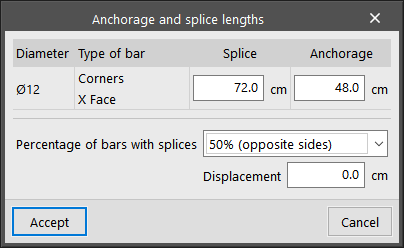
To edit the “Anchorage and splice lengths” of the reinforcement, click on the button to the right of the longitudinal reinforcement of the Y face. You can modify the “Percentage of bars with splices“. If the overlap is equal to 50% of opposite sides or alternating bars, you can apply a “Displacement” to it.
By clicking on the cell where the “Stirrups” are drawn, they can be edited. At the top, the diameter of the “Stirrups” is defined, and optionally, the “Crosstie diameter“. At the bottom, the program allows a specific layout of stirrups and crossties to be added from those available. The “Select a layout ” option can be used to preload a configuration of stirrups and crossties from the reinforcement tables.

Summary of code checks
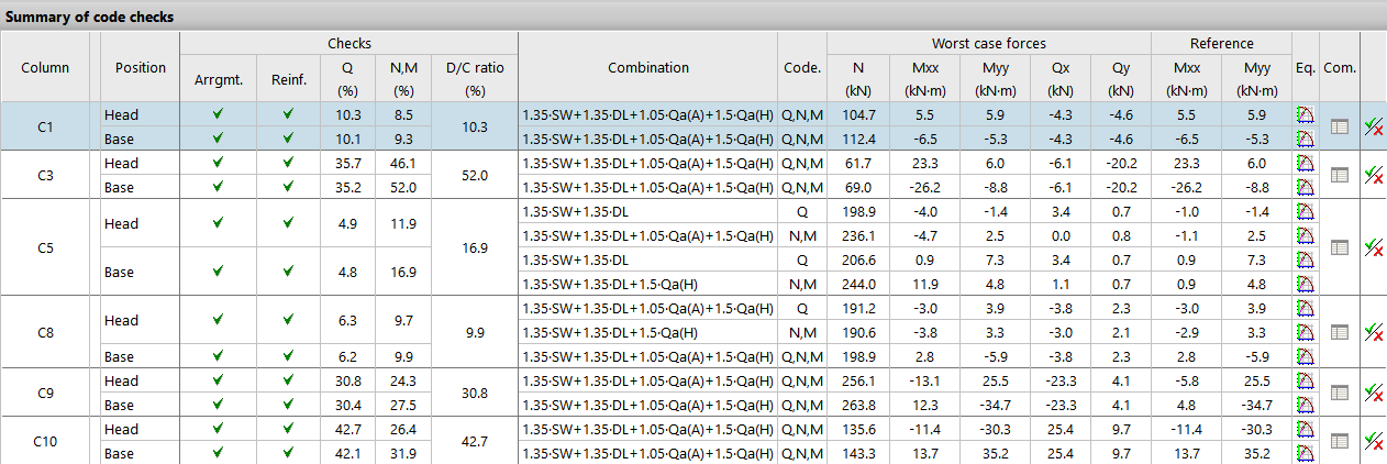
By selecting any row in the “Edit reinforcement” table, corresponding to a column span, the “Summary of code checks” section in the lower right-hand corner displays the information of the most relevant code checks for that column span.
For each “Column“, the “Position” of the check sections of the span, either at the “Head” or at the “Base” of the span, is indicated.
The different columns show the numerical values calculated for the most important “Checks“, including the maximum “Demand capacity ratio” of the section and the “Combination” of loadcases in which it occurs.
The “Worst case forces” are those with which the section has been reinforced, while the “Reference” forces are those obtained directly from the resolution of the matrix analysis and prior to operations such as the moment amplification.
On the right-hand side, the “Equilibrium diagram of the section for the selected combination” and the “List of the checks undertaken for all the combinations” are shown.
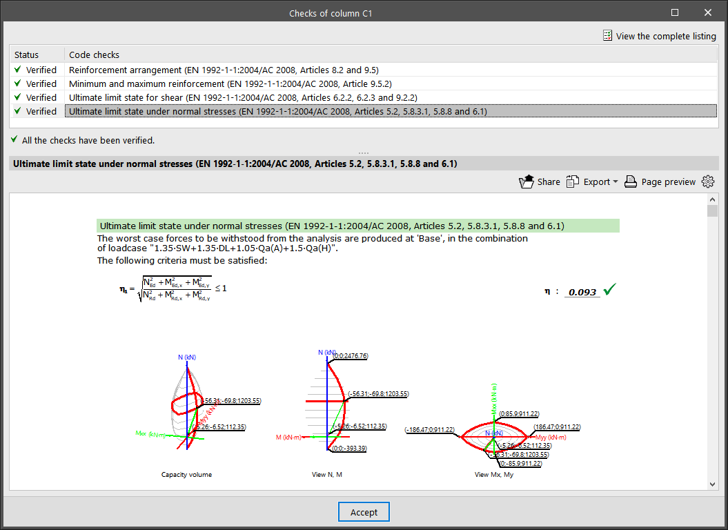
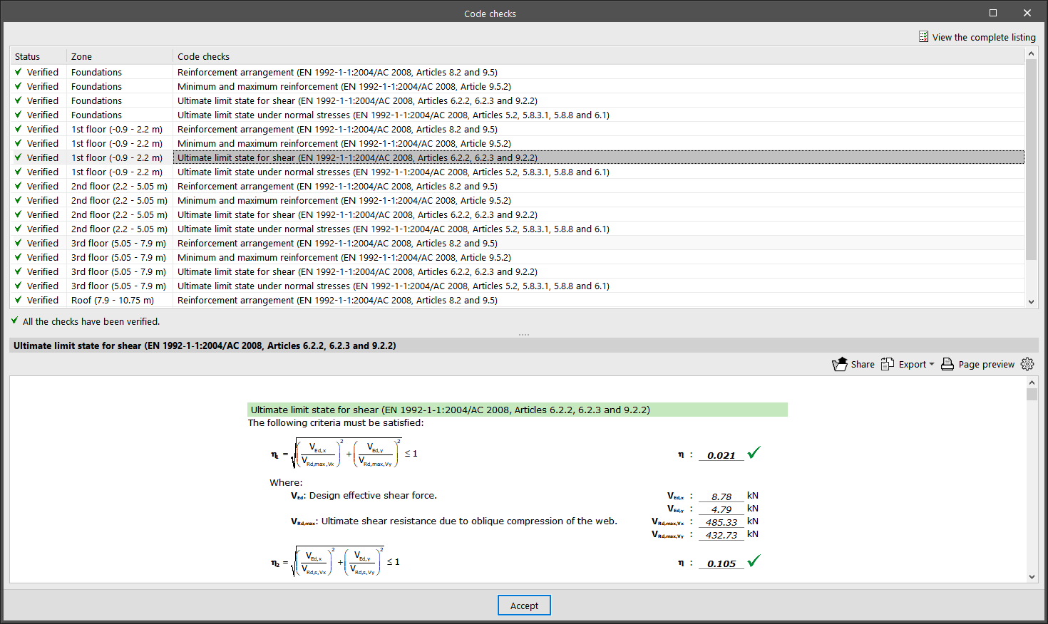
By clicking on the last button, you can access the list of “Code checks” for the selected column span. Here, all the checks carried out are displayed one by one, including a mark with their “Status“. At the bottom, the section or article of the verified code is indicated, as well as an explanation of the analysis that has been carried out for each one of them. For a detailed report of all the checks, click on “View the complete listing“. Users can “Export” the information in different formats, “Share” it or “Print” it.
Other options
At the top of the “Edit columns” window, there are a number of tools with different functions.
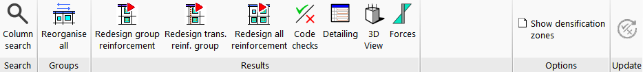
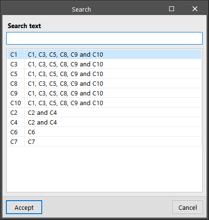
First, users can carry out a “Column search” by indicating its reference or they can click on “Reorganise all” to reorganise the groups of columns by their reference.
In the “Results” group, the “Redesign group reinforcement”, “Redesign trans. reinf. group”, or “Redesign all reinforcement” options allow the program to automatically retrieve the reinforcement of the selected column groups after any modifications using the available reinforcement tables.
The “Code checks” option allows users to obtain the list of ultimate limit state checks for all the sections of the selected column. Users can “Export“, “Share” or “Print” this information in the same way as the partial check reports shown above.
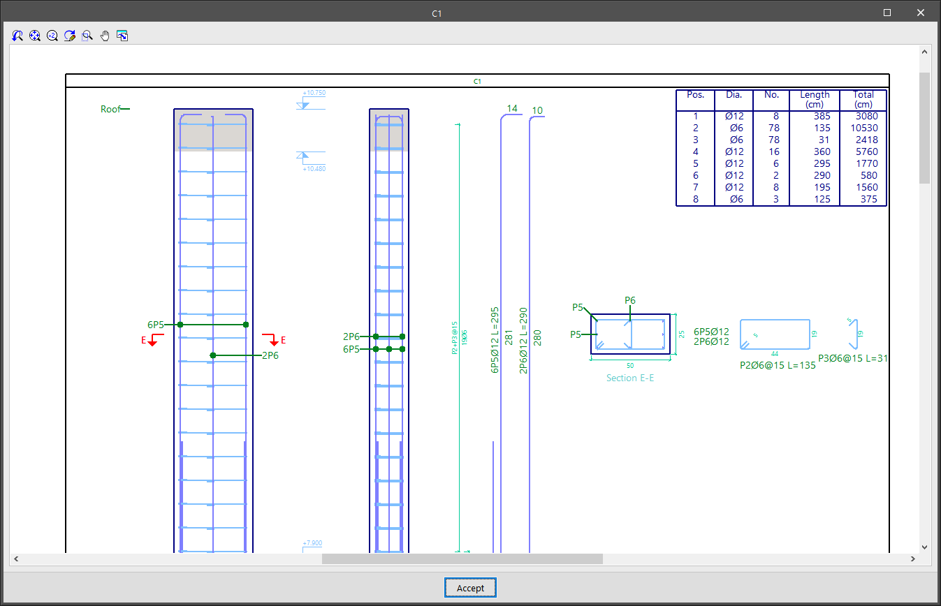
“Detailing” provides a view of the column with a detailed and dimensioned layout of all reinforcement, including their measurements in a table of ratios.
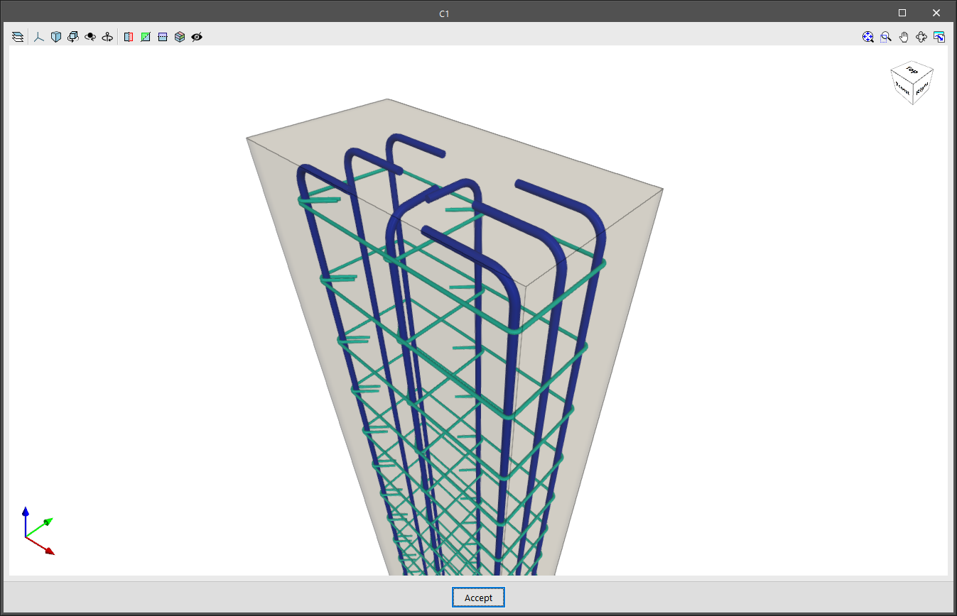
“3D View” shows the section and reinforcement of a column in a fully three-dimensional environment.
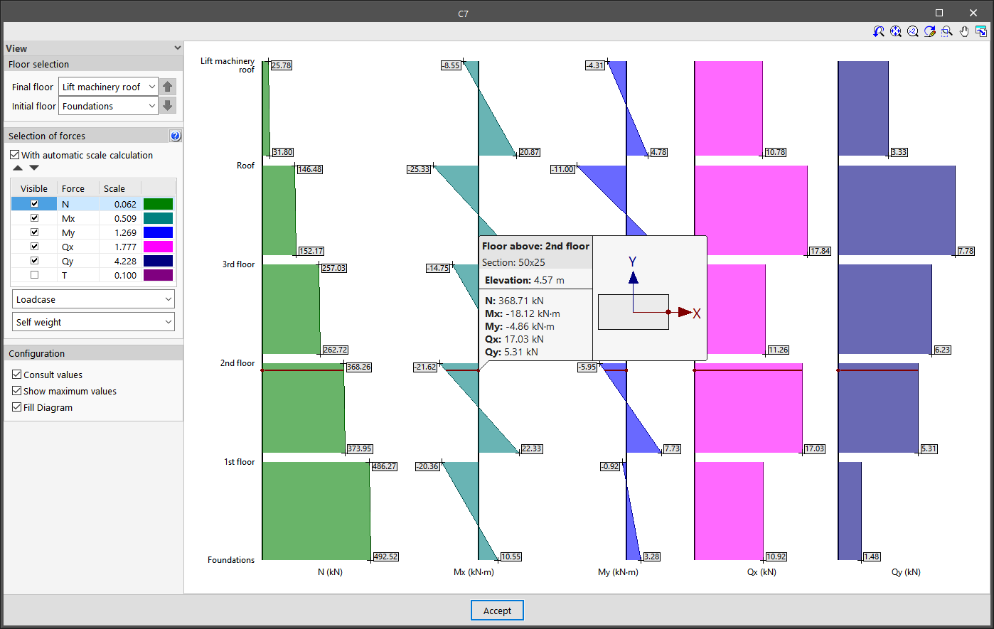
The “Forces” option allows you to view the axial, moment, shear and torsional diagrams of the selected column. To do this, the visible floors and forces are selected, as well as their “Scale“. The desired “Loadcase” or “Combination” can be selected from the drop-down menus. Then, by moving the mouse pointer over the diagrams, the program will display the information on the values of the forces for the section located at the indicated dimension and for the selected loadcase or combination.
The “Show densification zones” option shows or hides the different stirrup sections in the “Edit reinforcement” table that a concrete or composite column can have, depending on the options considered in the analysis. This option does not allow users to add any more different densification zones. To do so, they must go to the “Edit in column schedule“.
Finally, the “Update” option allows the check results to be updated after any changes have been made.
Lastly, it should be noted that if major modifications are made to column sections, a complete analysis of the job is recommended, as there may be significant variations in the forces to which they are subjected.