Customize Consent Preferences

We use cookies to help you navigate efficiently and perform certain functions. You will find detailed information about all cookies under each consent category below.

The cookies that are categorized as "Necessary" are stored on your browser as they are essential for enabling the basic functionalities of the site.... 

Always Active
Strictly necessary cookies are absolutely essential for the website to function properly. These cookies provide the basic functions and security features of the website, anonymously.
Functionality cookies help to carry out certain functions, such as sharing the website content on social media platforms, collecting feedback, and other third-party features.
Performance cookies are used to understand and analyse the key performance indicators of the website, thus helping to provide a better user experience for visitors.

No cookies to display.

Analytics cookies are used to understand how visitors interact with the website. These cookies help provide information on website metrics, such as the number of visitors, bounce rate, traffic source, etc.
Advertisement cookies are used to provide visitors with relevant ads and marketing campaigns. These cookies track visitors across websites and collect information to provide customized ads.

No cookies to display.

Other uncategorized cookies are those that are being analyzed and have not been classified into a category as yet.

No cookies to display.

Share

More information

Version

Associated programs:

Defining braced frames and ties

The conditions for the program to identify a braced frame are as follows:

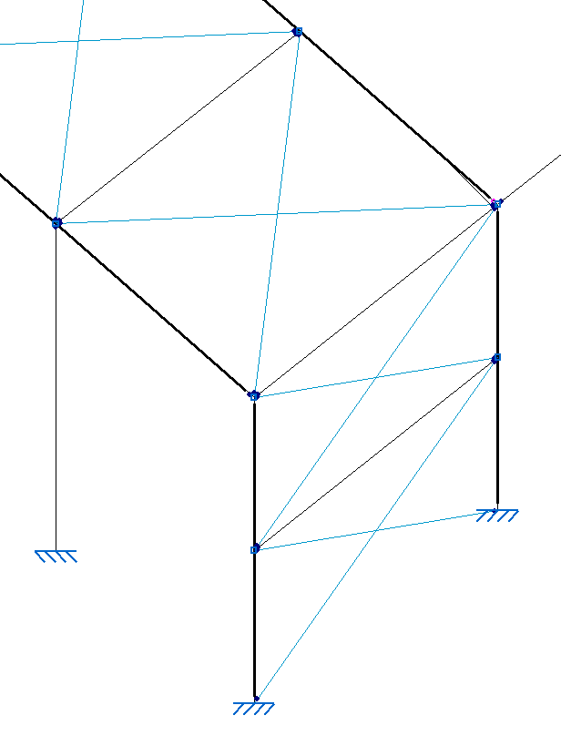
1. The frame must consist of four bars. It is also possible to define only three bars if the end of two of them is stiffened by an "External fixity", as in the case of a frame consisting of two vertical bars joined by a horizontal lintel.

2. The bars must belong to the same plane. If there are errors or inaccuracies in the drawing, one of the bars may come out of the plane.

3. The bars must form a rectangle, so the interior angles must be right angles. Similarly, any inaccuracies in the drawing may result in acute or obtuse angles.

4. There may be nodes on each of the sides of the rectangle, but in this case, users must use the "Bar" and "Create elements" options to create a single continuous element by clicking on the two vertices that form that side of the rectangle.

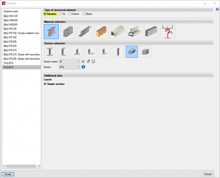
5. The bars forming the frame must be defined with the "Generic" structural element type under "Bar", "Describe".

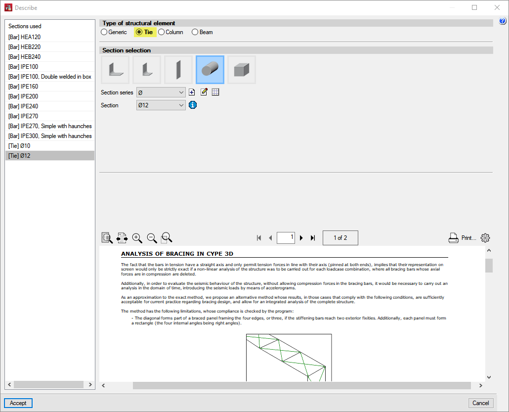
If all the above conditions are met, users may introduce two bars defined as "Tie" in the "Type of structural element" section under " Bar", "Describe", following the two diagonals of the rectangle.

If any of the above conditions are not met, bars defined as a "Generic" structural element type under " Bar", "Describe" can be used. This bar category does not require the existence of braced frames to complete the design: