In a hydraulic supply installation there are two types of vertical pipes:
- Vertical pipes with elevation changes on the same floor.
- Vertical pipes between floors or risers.
CYPEPLUMBING Water Systems considers both types and offers different ways of entering them:
Vertical pipes with elevation changes on the same floor
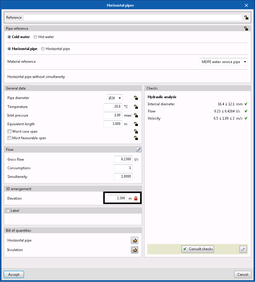
First of all, to enter a vertical pipe with elevation changes in the installation on the same floor, a horizontal section must be modelled at a certain elevation. Then, simply define a second horizontal pipe by placing it on the corresponding “Elevation” (different from the first section) and blocking it using the padlock button:
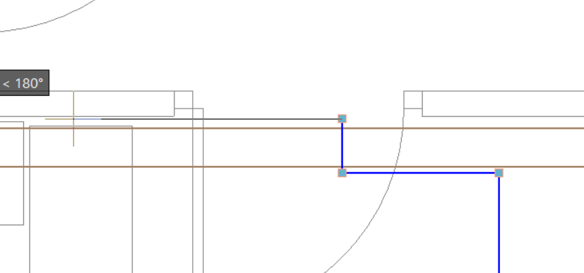
Next, this pipe is entered into the floor plan by clicking on the endpoint of the first section and then the modelling continues:
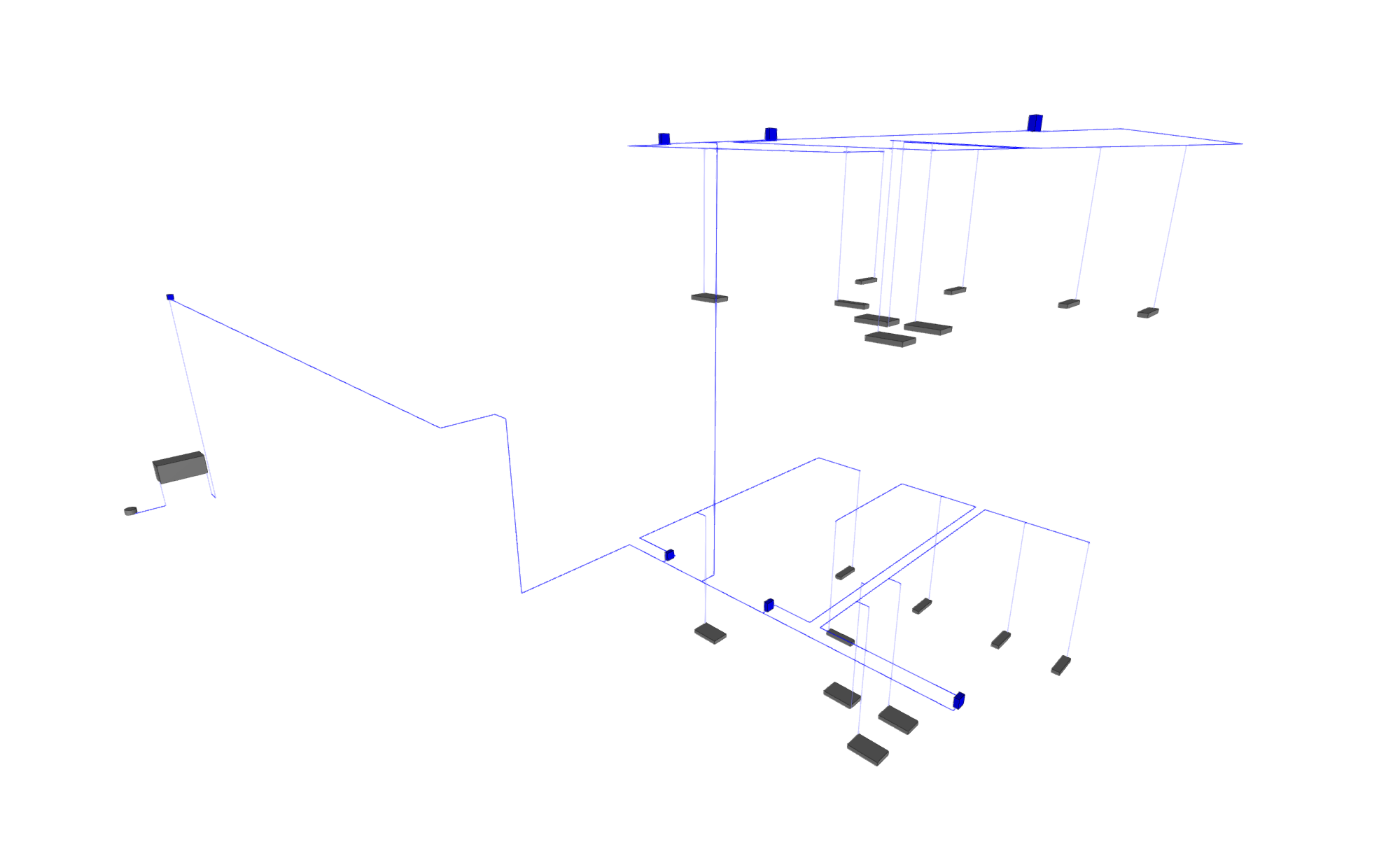
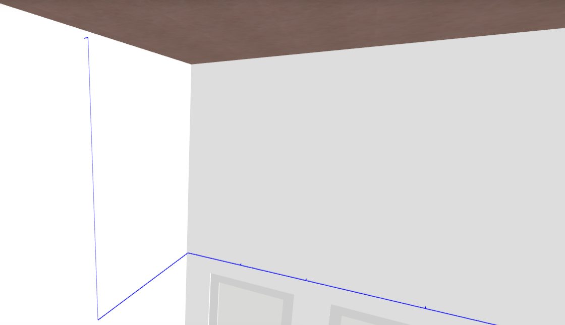
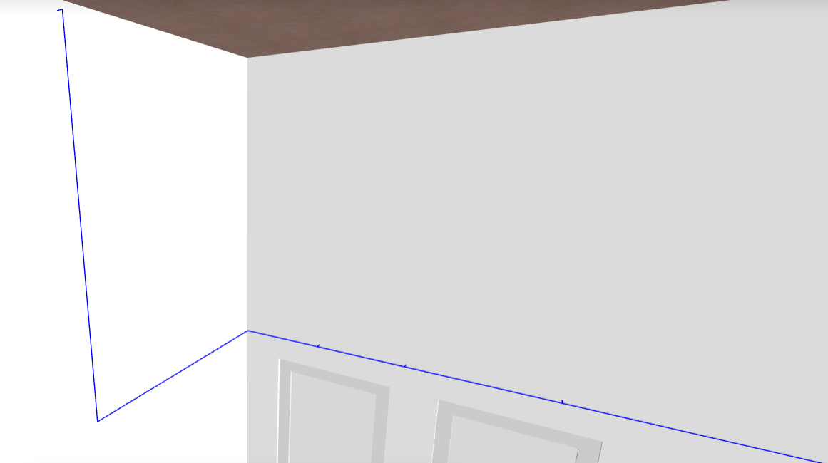
Once the analysis or design has been carried out, the programme will automatically enter a false vertical pipe that connects the two horizontal sections to different elevations. This pipe will be represented in a 3D view in a lighter shade and will have the same design properties as the horizontal pipe from which it has been created:
The second way of entering a pipe with elevation changes in the installation on the same floor is with the “Vertical pipe” option in the “Pipes” section in the top toolbar:

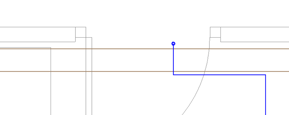
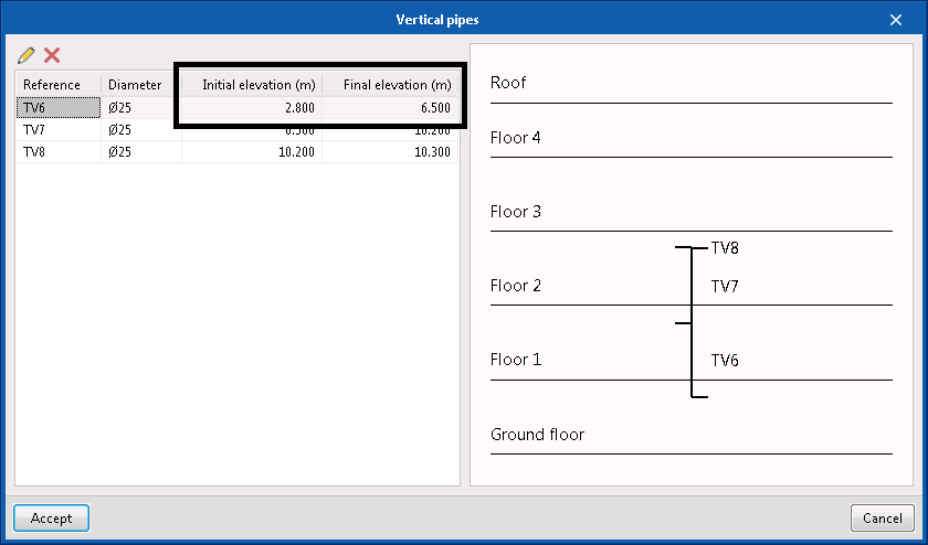
In this case, the initial horizontal section is entered by setting its height followed by a vertical pipe. The “Elevation” option is marked and the same floor for the “Initial elevation” and “Final elevation” is selected with the blue arrow. Once accepted, it will have the same initial and final elevation, so the “Final elevation” must be modified (i.e. by adding 1 metre), so that it does not have the same one and can be placed in the model.

AfteAfter accepting the window, the point in the model where the vertical pipe will be placed is indicated. This will be represented by a circle:
Finally, the horizontal pipe belonging to the following section of the installation is entered, and its height is also set to the desired elevation. This way, when calculating or designing the programme will detect and automatically connect the two elevation difference points in the model.
Unlike the previous procedure, in this case, the modelled vertical pipe has different properties from the horizontal pipes connected to it and its 3D representation tone is the same as the rest:
Vertical pipes between floors
The two aforementioned procedures are two ways of entering elevation differences in the installation on the same floor. Alternatively, the procedure for introducing risers or vertical pipes between floors is much simpler.
To do this, the “Vertical pipe” option in the top toolbar is also selected but, in this case, by marking the “Riser” option. Then, the blue arrow must be pressed in the “3D arrangement” section and the riser’s “Initial floor” and “Final floor” must be selected:
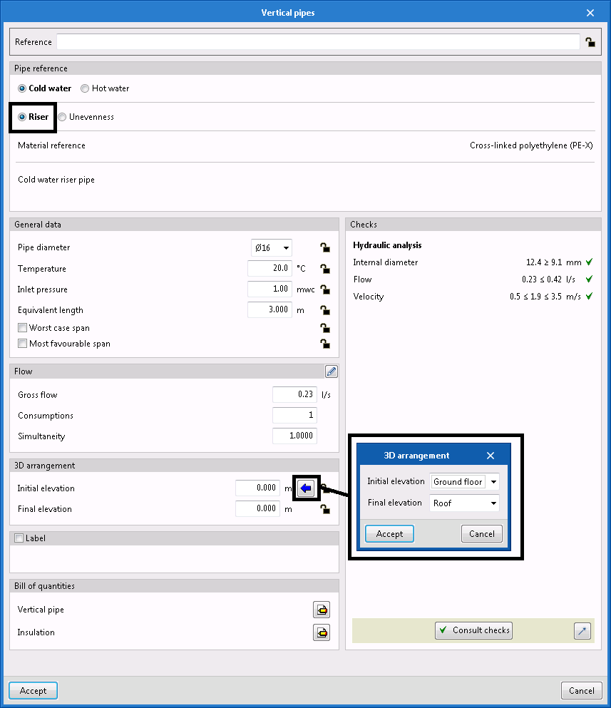
Once accepted, the 3D arrangement of the automatic configuration will be filled in. Without blocking the elevations with the padlock, the panel is accepted and the riser is entered into the model. This will be represented by a circle:
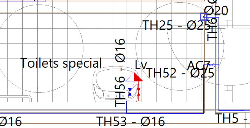
This circle will be represented on all floors the riser passes through, depending on the selected initial and final floors. The horizontal pipes can be connected later by setting their elevation on each of the floors.
Although the exact heights of the riser have not been defined, once the installation has been designed or analysed and as the elevations have not been set, the programme will automatically adjust the length of the riser, either extending it or shortening it, depending on the heights of both the horizontal pipe on the initial floor and the horizontal pipe on the final floor that has been selected:
The riser will be a separate pipe with as many different sections (with their respective properties) as there are connection points with horizontal pipes. Its representation is shown below: