
The following modelling recommendations in CYPE Architecture help to reduce the number of issues and errors after exporting to BIMserver.center and importing to other programmes such as Open BIM Analytical Model.
1. Assigning levels and typologies
All the elements in the “Architecture” tab, both architectural elements (walls, floor slabs, openings) and spaces, must be assigned to a certain level and typology.
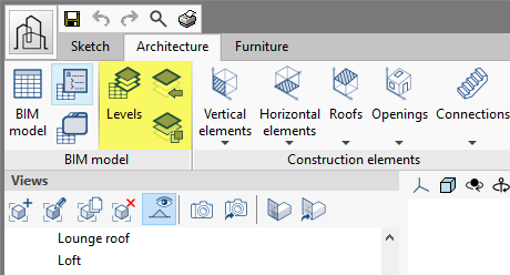
Typologies are created and managed from the “Typology of the architectural elements” menu in the top toolbar.
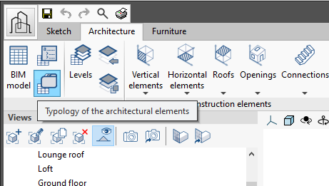
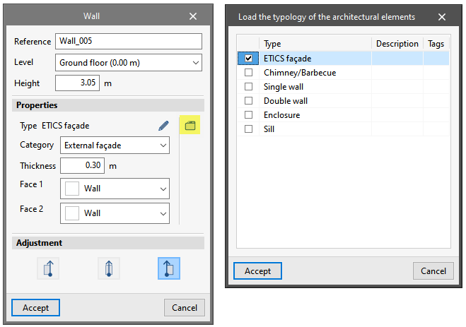
Then, they are assigned to elements by editing them and loading a typology with the button available on the right-hand side of the “Properties” section:
Levels can be created and assigned using the corresponding options in the top menu:
2. Model accuracy
For Open BIM Analytical Model to automatically generate the surfaces of the model, it is recommended that the surface of the volumes of the spaces in CYPE Architecture perfectly matches the surface of the inner or visible faces of the architectural models forming its outline. This implies the following:
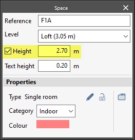
a) The lower and upper surfaces of the spaces must match the top face of the floor slab they are lying on and the bottom face of the floor slab they reach at the top of the wall.
To do this, users must check the position and parameter of the “Height” of the openings, corresponding with their free height:
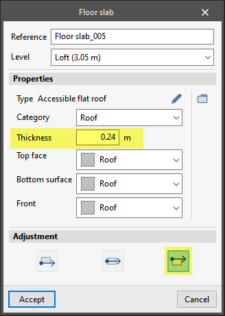
The “Thickness” and the “Adjustment” of the floor slabs must also be examined:
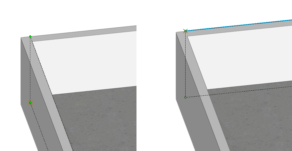
b) The lateral surfaces of the openings must match the inner faces of the walls and partitions surrounding the space. To guarantee this, the “Space by polyline” may be entered with the corresponding option in the top toolbar by activating only the “Intersection” snap.
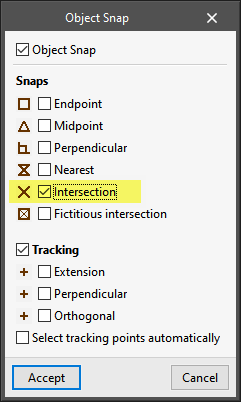
Then, in a 3D view, all intersection points of the trihedron corners formed by the two walls and the floor are selected in order to enter the vertices of the polyline and draw the space. It is recommended to orbit the model to continue entering the remaining points:

If there are inaccuracies in the position of the elements in the model, some surfaces of architectural elements that do not match the surfaces of the spaces may not be recognised by Open BIM Analytical Model.
3. Intersection solutions
In the “Edit” group, when using the options created for solving intersections and especially by using the “Intersection solutions” button automatically, uncontrolled geometries may be generated in some cases, such as intersections for partition walls entered imprecisely, angled connections between several partition walls, the presence of openings near the intersections, any existing unevenness or any other geometrical complexity.
If one of these cases occurs, users may “Regenerate” the affected elements with the button that allows this in the aforementioned section and thus undo the geometrical changes in the intersection solutions. Then, revise the geometry following precision criteria, deleting and re-entering architectural elements if necessary. The following modelling recommendations in CYPECAD MEP and IFC Builder can be taken as a reference. From there, if the intersection is placed correctly, the intersection solution options can be used. Also, for better control, manual intersection options are preferred over automatic intersection solutions.
You may also consider using geometries that do not require the use of intersection solutions at all. In the following image, the intersection between two walls that do not require the use of intersection solutions is shown. To do this, the position of the walls, their adjustment and their thickness with regards to the entry lines of both walls has been controlled.
In the image, the dotted-line polygon and green-coloured vertices correspond to the reference plans of each wall. These plans are raised on the entry lines defined on plan view when entering the walls “By polyline”. You can consult this reference plan via the “Edit geometry” option.